The intricacies behind wiring a modern car engine can become a daunting undertaking for most car owners. Trying to trace and understand the complexities of an internal combustion engine’s wiring can prove to be time consuming and complex, but understanding the correct wiring diagram is essential in getting the job done correctly.
For those who are just starting out on a wiring journey, or are seasoned professionals, it may be beneficial to look into the HZ Engine Wiring Diagram. Developed by a research team at Lawrence Livermore National Labs, the HZ system provides a comprehensive process to trace the full scope of wiring a vehicle’s internal combustion engine. Technicians and car owners alike will appreciate HZ’s use of detailed wiring diagrams that break down all the complexity behind wiring in the simplest form. This multifaceted approach allows users to troubleshoot any wiring problems quickly and efficiently, ensuring that cars and other vehicles get back on the road quickly and securely.
In addition to its complex wiring diagrams, the HZ system also offers an interactive wiring simulator. This allows users to test out their wiring prior to implementation, protecting against any potential errors. HZ’s easy to follow instructional videos make installation a breeze, providing a step-by-step guide that is simple enough for even the most novice car owners to understand. With the system's robust applications and user friendly options, it has proven to be one of the best resources available for modern wiring needs.
For anyone looking to understand the complexities of wiring a modern vehicle, the HZ Engine Wiring Diagram is the ideal solution. With its interactive wiring simulator and comprehensive diagrams, car and vehicle owners have a reliable way to troubleshoot any wiring issues. Efficient, simple and comprehensive, the HZ Engine Wiring Diagram is the perfect way to upgrade your wiring journey.

Figure Fo 6 Control Box Wiring Harness Diagram 400 Hz Sheet 2 Of 3
Fj40 Wiring Diagrams Ih8mud Forum
Colored Wiring Diagram For Mk1 1961 1963 Mg Midget Forum Experience Forums The
Wanted 1hz 1hdt Engine Electrical Sub Harness Wiring Loom Ih8mud Forum

Mega Ii Idle Air Control

Figure 4 21 50 60 Hz Governor Control Unit Schematic Diagram Drawing No 69 729
Installation Instructions For Dometic Family Rv A Cs

I Do Have A 1996 Polaris Sl700 Need Information Regarding The Ignition Control Module Is It Possible To New

Frequency Meter Counter 10hz 60mhz

Electric Motor Diagrams

Dr Premier 220v Electrically Operated Projection Screen Instruction Manual Manuals

Generator Wiring Diagram Westerbeke 8 0kw 60hz Operator S Manual Page 31 Manualslib

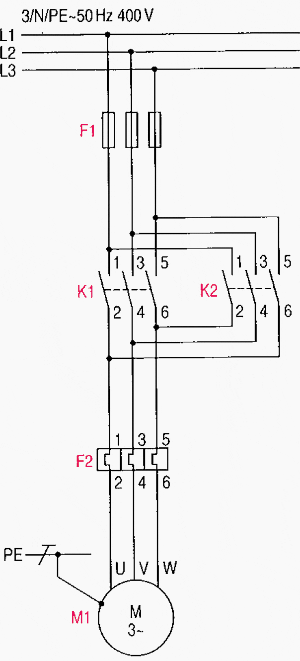
Main And Auxiliary Circuit Diagrams Of Switching Three Phase Motors Via Contactor Directly Eep

36 Node Network Wiring Diagram Scientific

Homelite Hh150 Portable E Heater Ut 65045 Parts Diagram For Wiring

Show Tell Ac Induction Motors

Unbranded M1 Wiring Diagram Manualzz
