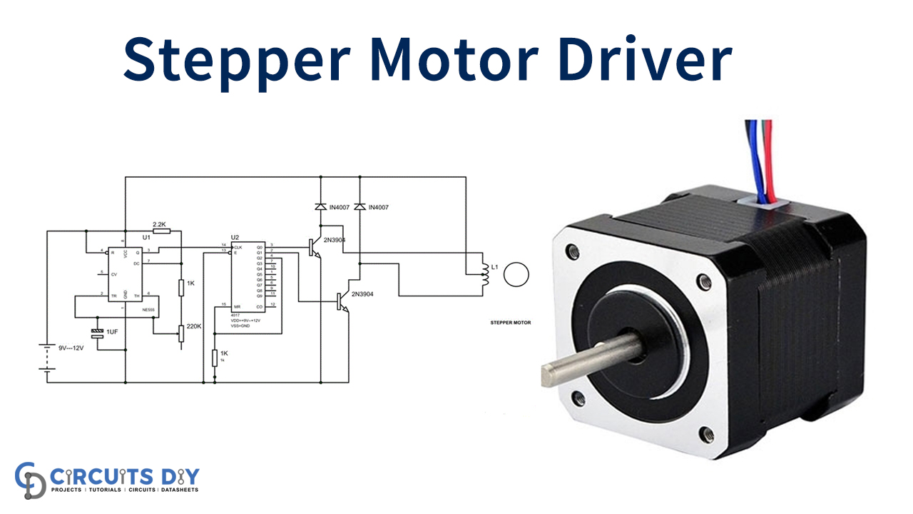
A bipolar stepper motor driver circuit is a device that is used to control the motion of a stepper motor, a type of electric motor optimized for precise movements in both directions. Unlike normal electric motors, steps move in discrete increments and can be programmed to execute complex motions involving many individual steps. A bipolar stepper motor requires both a positive and negative voltage in order to operate, which is why a driver circuit is often necessary.
The bipolar stepper motor driver circuit typically consists of several components, including power supply, voltage regulator, MOSFETs, switches, and a control logic. The voltage regulator monitors the voltage going into the circuit, ensuring that the right amount of power is supplied to each component. The MOSFETs act as electronic switches, controlling the current going to the motor itself. The switches enable the user to switch between forward and reverse operations, giving the motor its bi-directional capabilities. The control logic is responsible for monitoring and controlling the motor's movement, telling it how many steps to take and in what direction.
One of the main benefits of using a bipolar stepper motor driver circuit is the ability to quickly and accurately control the motor's movements. This makes the driver an ideal choice for applications involving precise movements such as 3D printing, robotics, automated assembly lines, and more. In addition, the circuit's compact size and durability mean that it can handle high workloads without compromising its performance. This makes it suitable for industrial applications where a reliable motor is required.
In conclusion, a bipolar stepper motor driver circuit is an essential component for controlling stepper motors that require precise movements. This driver provides accuracy, reliability, and durability, making it ideal for industrial applications and those that involve repetitive and intricate motions.

Simple Stepper Motor Driver Circuit Diagram Using 555 Timer Ic
Stepper Motor Driver 74194

Bipolar Stepper Motor Driver Circuit Diagram

Stepper Motor Controller

Driving Bipolar Stepper Motors

Stepper Motor

Bipolar Stepper Motor Driver Board A3967slb Development Tool Mikroelektronika

Stepper Motor Driver Circuit

Bipolar Stepper Motor Control With Arduino And An H Bridge 42 Bots

6 24v 2 5a 4 Wire Bipolar Stepper Motor Driver Kit

X And Y Axis Stepper Motor Driver Circuit As Shown In Fig 5 Two Scientific Diagram

H Bridge Driver For Two Phase Bipolar Stepper Motor

Stepper Motor Driver

Bipolar Stepper Motor Drive Circuit Diagram Under Circuits 59667 Next Gr

Bipolar Stepper Motor What Is It Circuit And Sequence Electrical4u

How To Play With A Salvaged Bipolar Stepper Motor Codrey Electronics

L297 Ir2104 Irfz44 High Power Bipolar Stepper Motor Driver Circuit Electronics Projects Circuits

Electronic Design

Stepper Motor Controller Circuit Diagram
